
I created a PMOD module PCB using KiCAD, that enables connecting WS2812B lighting strips to an FPGA board with a PMOD interface. The board was assembled by JLCPCB.
This is my first project using an FPGA, I plan to soon implement an SPI interface with the FPGA, to accept colour pixels via SPI from a raspberry pi, to then drive the LEDs appropriately. I am making use of the original Zybo board which uses a Zynq FPGA, although I’m not using the ARM portion of this chip as I want to learn VHDL.
I am currently making use of BRAM to store the colour data.
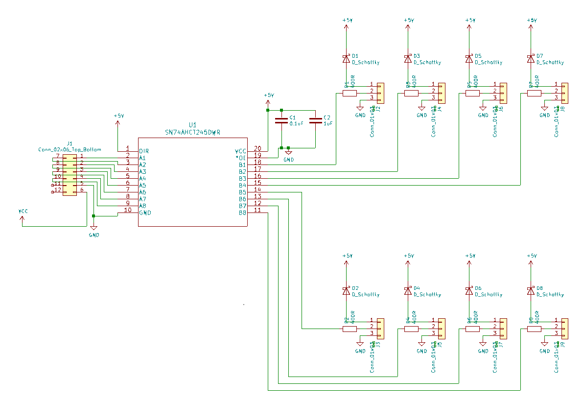
I made use of the 74AHCT245 chip to convert PMOD signals from the FPGA from 3.3V logic to 5V logic. This chip is powered by the 5V supply from the WS2812B led strips.
The board will support up to 8 LED strips.
I made use of 8x 2.54mm pin headers, for allowing connection of the LED strips. I attached dupont sockets to JST SM wires I bought, via a crimper, which connect the strips themselves to my board.

Schematic
As you can see below the schematic is very simple
The diodes are present so multiple 5V PSUs could be connected to the board, see https://www.edn.com/fundamentals-of-power-system-oring/ for more information.
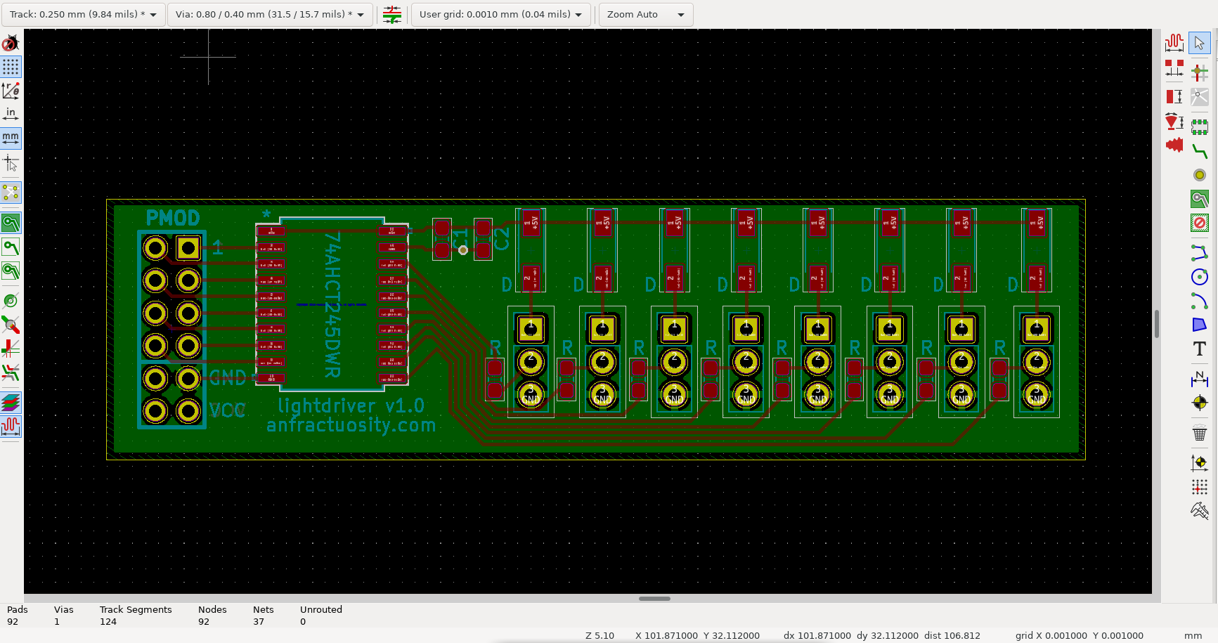
PCB
I made use of the PMOD connector footprint from https://github.com/mithro/kicad-pmod so I got the correct pin numberings and silkscreen, as well as allowing me to position the 2x 6 pin header towards the edge of the board correctly 🙂
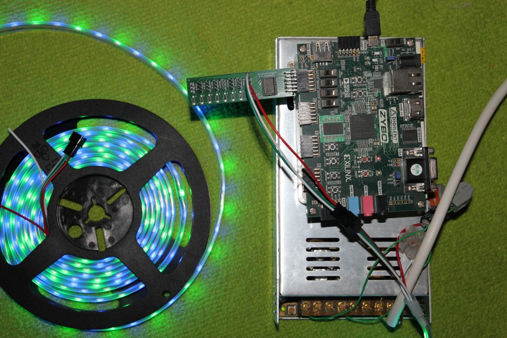
The following image shows the PMOD module connected to WS2812B lighting strips and my Zybo fpga board.
VHDL
I had a number of problems when creating the VHDL, one of which was an abnormal termination with Vivado during synthesis. This is a bug with Vivado which is currently still present in 2020.1, to fix this I was told to add the following, synthesis was then able to complete 🙂
attribute dont_touch : string;
attribute dont_touch of colour_counter : signal is "true";
I also ran into a bug with the time datatype where 32 bit floats are used rather than 64 bit, meaning precision is lost, the VHDL appeared to work ok in simulation but failed in implementation. I fixed this by making use of ‘real’ instead. See the xilinx forum for more information.
Also currently because I’m not using one of the Vivado 2020.1 supported OSs, I had to fake my /etc/os-release file to pretend to be Ubuntu 16.04, otherwise an exception would occur in the setup.
Originally I used 50uS for the refresh period, however I ran into issues with the display, after re-reading the datasheet it had to be greater than this value, I’m currently using 74uS. My calculations are based on the FPGA clock, which in this case is 125MHz.
library IEEE;
use IEEE.NUMERIC_STD.ALL;
use IEEE.STD_LOGIC_1164.ALL;
use IEEE.MATH_REAL.ALL;
use IEEE.MATH_REAL;

entity lighting is
port (
    clk: in std_logic;    -- 125MHz clock
    strip_1: out std_logic -- Output to first header pins on my PMOD board
);
end lighting;

architecture Behavioral of lighting is
    constant size: integer := 60 * 4;         -- Number of LEDs
    constant tp_clock: real := 1.0 / 125.0e6; -- Get time period, for 125MHz clock

    type ram is array(0 to (size*2)-1) of unsigned(0 to 23); -- allocate BRAM for double buffering
    signal vram : ram := (others => "000000000000000000000000"); -- initialise

    signal led_bits: unsigned(0 to 23) := "000000000000000000000000"; -- each LED is 24 bits, we output the same bitstream to all LEDs

    signal long: integer := integer(0.85e-6 / tp_clock);       -- long duration
    signal short: integer := integer(0.4e-6 / tp_clock);       -- short duration
    signal refresh: integer := integer((74.0e-6) / tp_clock);  -- refresh duration, when strip is driven low, MUST be ABOVE 50uS

    signal clock_counter: integer := 0;    -- Counts clock pulses
    signal led_bit_counter: integer := 0;  -- Counts the Nth bit of an LED's colour data (24 bits total)
    signal led_counter: integer := 0;      -- LED number we're sending data for
    signal pulse: integer := 0;            -- Keeps track if we are outputting a high

    signal spi_counter: integer := 0;         -- Counts the bit from SPI for the Nth bit of a single LED
    signal spi_frame_counter: integer := 0;   -- Data for the Nth LED
    signal spi_data: std_logic_vector(0 to 23) := "000000000000000000000000";

    signal vram_part: bit := '0';            -- Writing SPI data, to first or second part of BRAM
    signal vram_part_tmp: bit := '0';        -- mirrors above, for choosing where to read from BRAM

    signal colour_counter: unsigned(23 downto 0) := "000000000000000000000000"; -- Counters address of BRAM for writing to
    attribute dont_touch : string;                               -- Hack so synthesis works
    attribute dont_touch of colour_counter : signal is "true";   -- Hack so synthesis works

    signal read_addr: integer := 0;          -- Store address to read data from of double buffer
    signal write_addr: integer := 0;         -- Store address to write data to in double buffer

    begin

        fill_bram : process(clk)
        begin
            if rising_edge(clk) then


                if vram_part = '0' then
                    write_addr <= 0 ;
                else
                    write_addr <= size  ;
                end if;

                if colour_counter >= size then
                    colour_counter <= "000000000000000000000000";
                    vram_part <= not vram_part;
                else
                    if colour_counter = 3 then   -- mark specific LED
                        vram(to_integer(colour_counter)+write_addr) <=     "111111110000000000000000";
                    else
                        if colour_counter(0) = '1' then -- generate alternating pattern
                            vram(to_integer(colour_counter)+write_addr) <= "000000000000000011111111";
                        else
                            vram(to_integer(colour_counter)+write_addr) <= "000000001111111100000000";
                        end if;
                    end if;
                    colour_counter <= colour_counter + 1;
                end if;
            end if;
        end process fill_bram;


        write_leds: process(clk)
        begin
            if rising_edge(clk) then

                -- Counting clock edges
                clock_counter <= clock_counter + 1;

                if vram_part_tmp = '0' then
                    read_addr <= led_counter+size ;
                else
                    read_addr <= led_counter  ;
                end if;

                led_bits <= vram(read_addr);

                -- Check if we've reached end of LED strip
                if led_counter = size then
                    -- Check if we have finished refresh duration
                    if clock_counter > refresh then
                        clock_counter <= 0;
                        led_counter <= 0;
                        vram_part_tmp <= vram_part;
                    else
                        strip_1 <= '0';
                    end if;
                else
                    -- Check if at the end of a WS2812B '0' or '1'
                    if clock_counter > short+long then

                        clock_counter <= 0;
                        led_bit_counter <= led_bit_counter + 1;

                        if led_bit_counter = 23 then
                            led_bit_counter <= 0;
                            led_counter <= led_counter + 1;
                        end if;

                    elsif led_bits(led_bit_counter) = '1' and clock_counter > long then
                        strip_1 <= '0';
                    elsif led_bits(led_bit_counter) = '0' and clock_counter > short then
                        strip_1 <= '0';
                    else
                        strip_1 <= '1';
                    end if;

                end if;
            end if;
        end process write_leds;
end Behavioral;
Board design
https://github.com/anfractuosity/lightdriver
FPGA links
FPGA LUTs – I found this interesting regarding how the LUTs are formed in an FPGA for creating different logic operations.
Intel FPGA talk – I thought this introductory talk into fpgas was quite nice, covering the different logic elements etc.
Hamsterworks – Lots of really interesting VHDL projects (on archive.org, original site is now down alas)
Leave Comment
Error