

In this article we provide information on how to visually decode the data stored on a magnetic stripe card. We make use of the Q-View magnetic developer which contains 1-3um iron powder according to the datasheet.
We attempt to decode the 2nd track on the card, which is stored at 75 bpi, as opposed to 210 bpi for track 1. I would like to try to decode track 1 at some point, once I’ve taken microscope images of the stripe through a metallurgical microscope, as the image I obtained from my scanner doesn’t seem high enough resolution to decode this track.
Any magnetic fields on a magnetic stripe (either north or south) will attract the iron powder, which creates a visually observable pattern which we will decode.
Article [1] provides very useful information on how data is represented as magnetic fields on the card stripe. The phrack article [2] provides very useful information on the ISO standard used for representing data on bank cards.
I wrote the following artificial data to a magnetic stripe (the data was obtained from the Phrack article), using an MSR605 card reader/writer.
Track1:%B1111222233334444^PUBLIC/JOHN?
Track2:;1111222233334444=9912101000000000000?
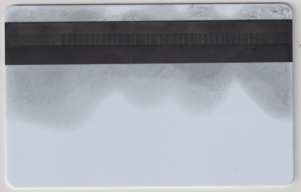
The image to the right represents the magnetic stripe after the Q-View liquid has been applied:
This image below represents the magnetic stripe after our algorithm has been run on it, we first make use of simple thresholding, so that the
image is binarized.
We make use of a very simple algorithm to perform the processing, we simply count the number of ‘red’ pixels in a column, we
do this process for all columns, in order to find the magnetic stripes.
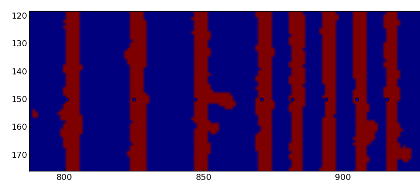
After this process is completed, we only store the distance of the first marker for each magnetic line relative to coordinate 0.
We then output a bitstream of 1s and 0s, based on the distance between stripes.
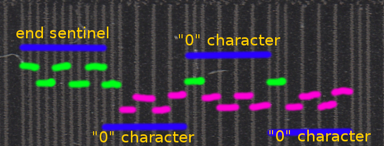
We loop through this bitstream to find the ‘end sentinel’ character, and then decode and print
the appropriate characters from their 5 bit encoding (the 5 bit encoding includes a parity bit).
Note: As we are reading the card left to right, the bits of the characters are in their reverse order.
The following image represents how 1s and 0s are encoded on the stripe
When running the program on the enclosed stripe, it should print ‘;1111222233334444=9912101000000000000?’.
Addendum:
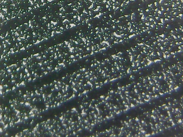
I was wondering if I could image part of a floppy disk, but from what I can tell with my limited experimentation the 1-3um iron powder in solvent may be too big, to give a high enough resolution image.
50x view of a floppy disk
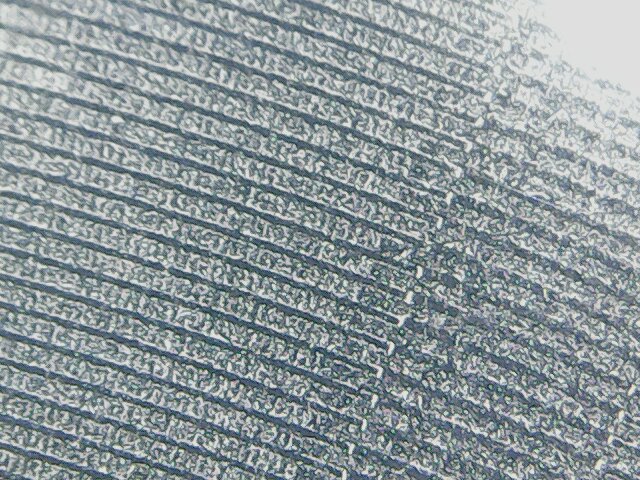
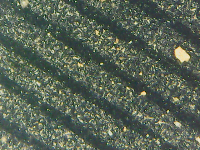
500x view of a floppy disk
ToDo:
When I’ve got time I’d like to image Track 1 of the magnetic stripe using a microscope which will require stitching of multiple images, hopefully through the use of Hugin.
I’m also wondering how difficult it would be to make a simple Magneto-optic Kerr effect microscope.
I just found you can get iron nanoparticles around 30nm, which I may try and obtain sometime 🙂
Iron Nanoparticles (I obtained 30nm nanoparticles but couldn’t seem to get much better images of a floppy disk)
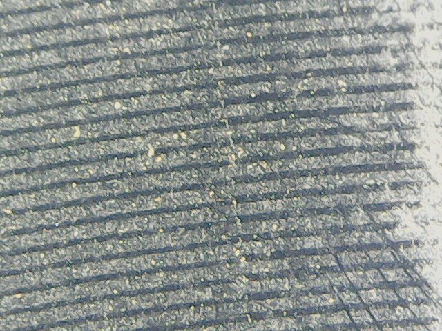
500x view of a floppy disk
50x view of a floppy disk
Please click here for the sourcecode.
[1] http://dewimorgan.livejournal.com/48917.html
[2] http://phrack.org/issues/37/6.html
3 Comments
Leave Comment
Error
Dewi Morgan
Oh wow, that’s VERY cool! Great job.
Interested in how you get on with the floppies, too.
Richard Kim
I’m wondering you can read my answer in here.
Are those images of 50x and 500x view of a floppy disk measured by magneto-optic kerr effect microscopy?
Did you treat something on that surface to measure magneto-optic kerr effect microscopy image?
admin
Hi,
No, they’re just from using the Q-View magnetic developer & iron nanoparticles, which I don’t think give fine grained enough detail for floppy disks unfortunately and then just imaged with a cheap usb microscope.
I would like to play with something like https://matesy.de/en/products/magnetic-field-visualization/applications/magnetic-stripe-card-quality-control-and-forgery-investigation
(Matesy Magview) which if I recall correctly uses the Faraday effect. But that’s not cheap.